Gurukul: The Silent Instruction
By Team Cryptonite · 3 min read
About the CTF: Pinaka CTF
The gate wants an eight-byte "mantra" and a trace tag. The firmware checks each mantra byte with one linear equation mod 251, so the mantra can be solved directly and the real emulator supplies the tag.
**Pinaka CTF 2026** · Reverse engineering · Team Cryptonite · All 44 Pinaka write-ups
Category: reverse engineering
Flag: PINAKA{gurukulthesilentinstructionis_sounded}
Overview
The gate wants an eight-byte "mantra" and a trace tag. The firmware checks each mantra byte with one linear equation mod 251, so the mantra can be solved directly and the real emulator supplies the tag.
Files:
vac_emu: stripped x86-64 PIE, the VAC emulatorfirmware.rom: 904 bytes, the firmware the gate acceptsfirmware_v1.rom: decoy variant, 16 code bytes differcalibration.dat: 1032 bytes, never read byvac_emu
./vac_emu firmware.rom 23 86 21 23 124 206 180 138
Analysis
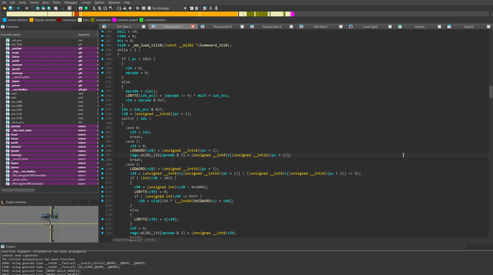
vac_emu is a small VM host. The main loop is at 0x1120 and the trace hashing routine is at 0x2140. The firmware is a stream of 24-bit instructions. The machine has 4 general registers, an accumulator and a mode register. ROM sits at 0x0000 to 0x03ff, there are four banks of 256 dwords at 0x4000 to 0x40ff (selected with setbank), some memory-mapped peripherals, and a bell timer that raises an interrupt.
State-dependent dispatch. The same opcode byte means different things depending on the current mode:
seed = [0, 5, 9, 2, 11, 4, 7, 1]
idx = (seed[mode] + (opcode >> 4) * (2 * mode + 1)) & 0xf
idx 0 to 14 map to:
0 nop    1 ldi    2 ld      3 st      4 mov     5 add     6 sub     7 mul
8 xor    9 setmode 10 rd    11 wr     12 jmp    13 jz     14 setbank
idx 15 is special: low nibble 0 is halt, 1 is ret (pop saved state), anything else is a nop. The opcode's low nibble picks a register r0 to r3. For mov, the low nibble is the source and the high nibble is the destination, with 4 meaning the accumulator.

also:
dword_30C0: seed tabledword_30E0: multiplier table.
Base-251 arithmetic. A 16-bit value is two base-251 digits. add, sub and mul reduce each digit mod 251, and only xor is plain 16-bit XOR. Modelling add as ordinary 16-bit addition makes the firmware checks unsolvable.
Peripherals:
rd 0: next mantra byterd 1: bytes remainingrd 2: sequence[10, 19, 28]rd 0x11: bell valuerd 0x31: activated flagwr 0x10: bell period, 0 disableswr 0x20: append a byte todeepawr 0x30: activate, only when the value is0xa5
Bell timer. The counter ticks on every retired instruction while enabled and not inhibited. On expiry it pushes pc, mode, registers, accumulator, bank and the zero flag, forces mode 0, and jumps to 0x380. That handler reads the bell value and stores it at bank0[0x10], and ret clears the inhibit latch and restores the mode. The bell value updates as v = (v*v + 0x1d) % 251, starting at 0x3b.
Firmware logic. Mode 0 setup copies ROM[0x340..0x34f] into bank1[0..7] and bank2[0..7], sets the bell period to 7, and switches to mode 2. Modes 2 and 3 then run eight checks, one per mantra byte:
acc = mantra[i] * bank2[i] + bell_i - bank1[i] (base-251 digits)
Any nonzero result sets r3 = 1. If all eight are zero, the firmware writes 0xa5 to peripheral 0x30 and . to peripheral 0x20, then halts. The tables:
bank1 = [100, 7, 222, 45, 130, 88, 199, 11]
bank2 = [2, 3, 5, 7, 11, 13, 17, 19]      # primes
bell  = [54, 0, 117, 135, 21, 171, 151, 150]
Solution
Each check is a linear congruence mod the prime 251:
mantra[i] = (bank1[i] - bell_i) * inverse(bank2[i]) mod 251
bank1 = [100, 7, 222, 45, 130, 88, 199, 11]
bank2 = [2, 3, 5, 7, 11, 13, 17, 19]
bell  = [54, 0, 117, 135, 21, 171, 151, 150]

mantra = []
for i in range(8):
    inv = pow(bank2[i], -1, 251)
    mantra.append(((bank1[i] - bell[i]) % 251) * inv % 251)

print(mantra)
# [23, 86, 21, 23, 124, 206, 180, 138]
The tag is a SHA-256 over a byte stream: prefix "VAC1" 0x33 0x00, one 4-byte record per retired instruction (pchi, pclo, dispatchidx, modeafter), the 7-byte marker 00 "DEEPA" 00, the deepa bytes, the activated byte, 0x80, zero padding to 56 mod 64, and a big-endian 64-bit bit length. The length field excludes the 0x80 byte, so the padding is non-standard. Instead of reimplementing it, run the real emulator:
./vac_emu firmware.rom 23 86 21 23 124 206 180 138
activated=1
deepa=2e
tag=fa794a8caf8596350aaa43ba2367385cf904397c85bf52cd0e8d68f20746371e
Submission
curl -s -X POST https://pinaka-a02-cyber-xo-x.vercel.app/gurukul/activate \
  -H 'Content-Type: application/json' \
  -d '{"mantra":[23,86,21,23,124,206,180,138],"trace_tag":"fa794a8caf8596350aaa43ba2367385cf904397c85bf52cd0e8d68f20746371e"}'
{"status":"activated","flag":"PINAKA{gurukul_the_silent_instruction_is_sounded}","proclamation":"The silent instruction is received; the gurukul opens its gate."}
Notes
firmware_v1.romhas 16 different code bytes, nonzero data at0x1a0+, and an interrupt handler that stores the bell at0x40f8instead of0x4010. The recovered mantra doesn't activate it.calibration.datis never opened, sincevacemuonly readsargv[1]. It starts with the ASCII headerVCAL, then0d 00 00 01, then 1024 bytes. XORing it withfirmware.romdoesn't givefirmwarev1.rom, and it contains neither the mantra nor the bank tables.- The ROM has a fake flag at
0x300:PINAKA{thespokenmantraisadecoykeepreversingthe_silence}. The firmware reads the 16 bytes right after it, at0x340, as its check tables.
